Robert G Kelly, AT&T Professor of Engineering at the University of Virginia, explains why we must understand when significant corrosion damage can occur to stainless steel canisters containing spent nuclear fuel.
Independent of one’s view on the future of nuclear energy, in the United States alone there are currently over 80,000 MT of spent nuclear fuel (SNF) stored in over 3,000 welded stainless steel dry storage canisters (DSC) at independent spent fuel storage installations (ISFSI). The ISFSI are co-located with the nuclear power plants that generate the SNF. These canisters have been emplaced inside concrete overpacks designed to allow passive cooling to occur. The SNF remains radioactive and will so for many thousands of years. It awaits decisions on and construction of a permanent repository – a process that is currently at a standstill in the United States. The U.S. Nuclear Regulatory Commission initially licensed these containers for a 20-year service life under the assumption that a permanent repository would be ready to receive them before that license expired. Some of the earlier containers are approaching the end of the license period, and both owners and regulators are in the process of developing criteria to allow relicensing for periods of up to another 20 years.
At ISFSI, located in near-marine environments, the cooling air drawn from the outside contains sea salt aerosols and other material. Upon encountering the hot steel surface, the aerosols will deposit. These aerosols will contain aggressive ions, including chloride ions, as well as oxidising species. They can also develop very low surface pH values. Such aerosols can be transported hundreds of miles inland, with decreasing deposition rates with increasing distance from the coast.1 Initially, after emplacement of the DSC into the concrete overpack, the DSC surfaces will be at a high enough temperature (~150-200˚C) that any aerosols deposited will be dry. Under these conditions, no aqueous corrosion can occur. Eventually, the canister will cool sufficiently, and the deposited salts will deliquescence.1
The corrosivity of the solution formed upon deliquescence will depend on the chemical constitution of the deposits, the concentration of the resulting solution (which depends on the temperature and relative humidity), the solution volume, and the extent of oxidizing gases (e.g., oxygen, ozone) present. Stainless steels exposed to such brine environments are susceptible to pitting, crevice corrosion, and stress-corrosion cracking (SCC) at sufficiently high stresses.2 Each of these damage modes is potentially serious, but the occurrence of corrosion pits leading to SCC is considered the most likely failure mode for DSC given the high stresses that can exist near welds.3 A means of assessing the likelihood of corrosion damage would be helpful in the relicensing discussions.
Challenges of corrosion prediction over long times
Accurate, quantitative prediction of pitting corrosion damage development for corrosion-resistant alloys, such as stainless steels, in service conditions remains a grand challenge for the field of corrosion science and engineering. The stochastic nature of the initiation of pits, combined with the time-varying nature of most service environments, has severely limited the success of spatiotemporal modelling of pitting corrosion. For service time periods of interest on the order of decades or longer, there is no validated spatiotemporal prediction model for pitting in stainless steels. These service times are those of relevance to both DSC and storage in a permanent repository.
There have been a multitude of studies of the factors controlling the initiation of pits and their dependence on environmental, metallurgical, and mechanical variables. In all cases, the rate of pit initiation is proportional to the surface area exposed, with values usually in the range of > 10-6 pits/cm2-sec.4,5 Thus, for surface areas relevant to DSC (> 105 cm2 per canister), it is virtually certain that many pits will initiate over a 20-30-year service life after deliquescence. Thus, any safety case based on an absence of pit initiation would not be conservative. At initiation, pits are sub-micron in diameter – a size range that is irrelevant to crack growth in SS with fracture toughness values of > 100 MPa-m1/2 even for stresses at the yield strength. Thus, pit growth is the critical stage for pitting in terms of DSC service life.
Spatiotemporal modelling of pit growth has, like pit initiation, been the subject of many studies.6,7 Most of these studies have either been aimed at short (< 1 day)6 or long (up to 20 years) periods.7 Short-term modelling has usually focused on laboratory measurements under highly controlled conditions, whereas the long-term modelling has focused on the empirical fitting of pit size observations on materials exposed to natural environments to power law descriptions. Extrapolation of the short-term data predicts pit sizes that are nonsensical (e.g., 18 cm (7”) deep pits in one year).8 Potentiostatic conditions represent those that a pit would experience in service with an infinite-sized cathode, which is not the condition pits on the surfaces of DSC would encounter. In addition, most pit growth studies have used potentials that are not achievable under service conditions.
Although fewer in number, studies of pit growth in service environments (typically seacoast) have focused on the establishment of empirical power laws of the form dpit=Atb. Extrapolation of empirical power laws developed via short testing times to the orders of magnitude longer times relevant to applications would be unwise. Extension of the long-term data to other environments, materials, and mechanical states is not feasible as there is insufficient understanding of, and data on, the natural environment conditions to connect the pit growth parameters to fit to other environments. Thus, each material/environment combination requires data to be collected at least as long as the service life of interest. In the case of DSC, such an experimental programme is not compatible with the schedule required to make inspection and licensing decisions.
The pitting models described above assume no limit exists for the size of a corrosion pit. However, data from long-term exposures of stainless steels to natural environments support the existence of maximum pit size for a range of materials.9 The concept of a limiting pit size is attractive as a means to incorporate the pit damage into the evaluation of the long-term structural integrity of engineered structures. Worst-case scenarios can be considered and, if mechanistically understood, parameters most important in driving the size of the limiting pit can be determined. This approach can also be coupled with fracture mechanics modelling of crack propagation to allow predictions of SCC or corrosion fatigue (in cases in which the stress is not static). Such an approach is reasonable to consider for DSC life prediction.
A bounding approach for pit size
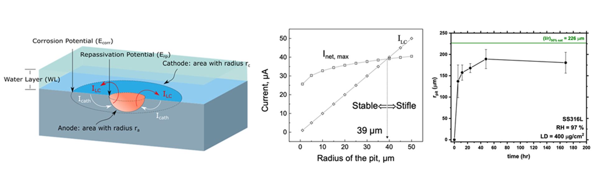
Researchers at the University of Virginia (UVA) developed a model that predicts the limiting, or maximum, pit size that can develop under known atmospheric conditions.9 Its predictions have been validated for stainless steels under laboratory conditions.8 The maximum pit size model calculates the values of the minimum pit current needed to maintain pit growth (ILC) and the maximum cathodic current the surrounding surface can provide (Icath) to define rpit,max, as shown in Fig. 1a. Hemispherical pits cannot grow beyond a radius of rpit,max because there is insufficient cathodic current available to consume the electrons released by the dissolution reaction that is needed to maintain the critical chemistry. This size limit is insurmountable for such pits as it is based on the conservation of charge. Pits of size less than rpit,max can propagate because the amount of cathode current available exceeds the minimum current needed for further growth. The values for ILC and Icath are determined from electrochemical measurements and by linking electrochemical kinetics with a knowledge of the amount and type of salt on the exterior surface, T, and RH.10
Coupling to cracking
SCC is known to initiate from pitting damage for SS materials in atmospheric environments.11 Extensive, detailed work on the pit-to-crack transition has been performed to better understand the fundamental mechanisms of crack initiation from pits. Such efforts require far too much in terms of labour and data needs to offer a reasonable path for engineering implementation. However, the understanding gained from these efforts enables critical evaluation of the effects of assumptions inherent in commonly applied engineering-scale approaches on the ability to provide accurate prediction of the pit-to-crack transition.
Kondo et al.12 proposed an engineering-scale method that is widely and successfully used to predict the pit-to-crack transition: the pit is assumed to be an equivalent-sized fracture mechanics (FM) crack and the pit-to-crack transition occurs when the calculated stress intensity (K) exceeds the threshold for stress-corrosion cracking (KISCC), and the crack growth rate exceeds the pit growth rate. Despite lacking complete mechanistic rigor, recent efforts have leveraged the extensive mechanistic research on the pit-to-crack transition to understand, justify, and establish boundaries of applicability for FM-based approaches (i.e., Kondo) for use in engineering analyses13–15. As such, coupling the Kondo and limiting pit size approaches provides a powerful framework to assess the effects of key environment- and location-specific parameters on the maximum pit size and the propensity for these pits to initiate SCC for various levels of loading.
The coupled Kondo and maximum pit size approach to modelling crack initiation and the SCC crack model for crack propagation both are critically dependent on the ability to generate a crack growth rate (da/dt) versus K relationship that is relevant for the material, loading conditions, and environmental conditions of interest. Recently, UVA has pioneered a robust protocol for such characterisation of the da/dt versus K relationships on various materials in full immersion environments using high-fidelity FM testing (akin to ISO7529-9).16 This accelerated laboratory testing method uses direct current potential drop (dcPD) to provide real-time, high-fidelity (≈1 µm) measurement of crack extension in a pre-cracked single edge notch (SEN) specimen in the environment of interest. Such testing under controlled-constant dK/dt has been successfully applied to a wide variety of steels, Al-based, and Ni-based alloys.17 Until recently, the bulk of the SCC research using this protocol has been performed with specimens fully immersed in an electrolyte of constant composition.16 Critically, these full immersion environments may not be representative of atmospheric service conditions for DSCs that are often typified by a deliquesced, thin-film electrolyte which leads to lower volumes of corrosive solution around the crack tip. Recent efforts at UVA have successfully extended the dcPD-based FM testing to various atmospheric-relevant environments.18
This unique coupling of FM testing, atmospheric environments, and local potential measurements enables quantification of KISCC, isolation of the crack growth stage, and generation of crack growth kinetics rapidly (<1-week tests) in environments relevant to the DSC. Such data will enable enhanced understanding of the damage process and its sensitivity to variables of interest for DSC. Furthermore, these da/dt versus K are the needed inputs to probabilistic FM lifting codes that predict the crack progression for various loading, material, and environmental combinations. This approach has been successfully applied to various engineered systems and could profoundly impact risk management of DSC via probabilistic life predictions, analytical evaluations of mitigation strategies, and evaluation of ‘what-if’ scenarios. Note that the goal of this modelling effort is not to solve DSC cracking issues, but rather to establish relevant SCC data to inform the location-specific risk to failure and engineering tools to enable rigorous management of any problem areas.
Uncertainty quantification
The basis of the modelling code developed by VEXTEC is the well-established FM concept of similitude, where for a constant crack tip driving force (i.e., K) and loading environment, there will be a constant material response (i.e., da/dt). This similitude enables extension of the growth rate data obtained in the laboratory to component/crack geometries and loading conditions relevant to DSC applications. Furthermore, adaptive Monte Carlo techniques are used to account for the variability and uncertainty in the input parameters. Specifically, various input parameters can be input as statistical distributions – these include the da/dt versus K relationship, atmospheric environment, initial defect size, applied stress, and residual stress. A temporal integration of the da/dt versus K relationship then enables prediction of the crack extension as a function of time.
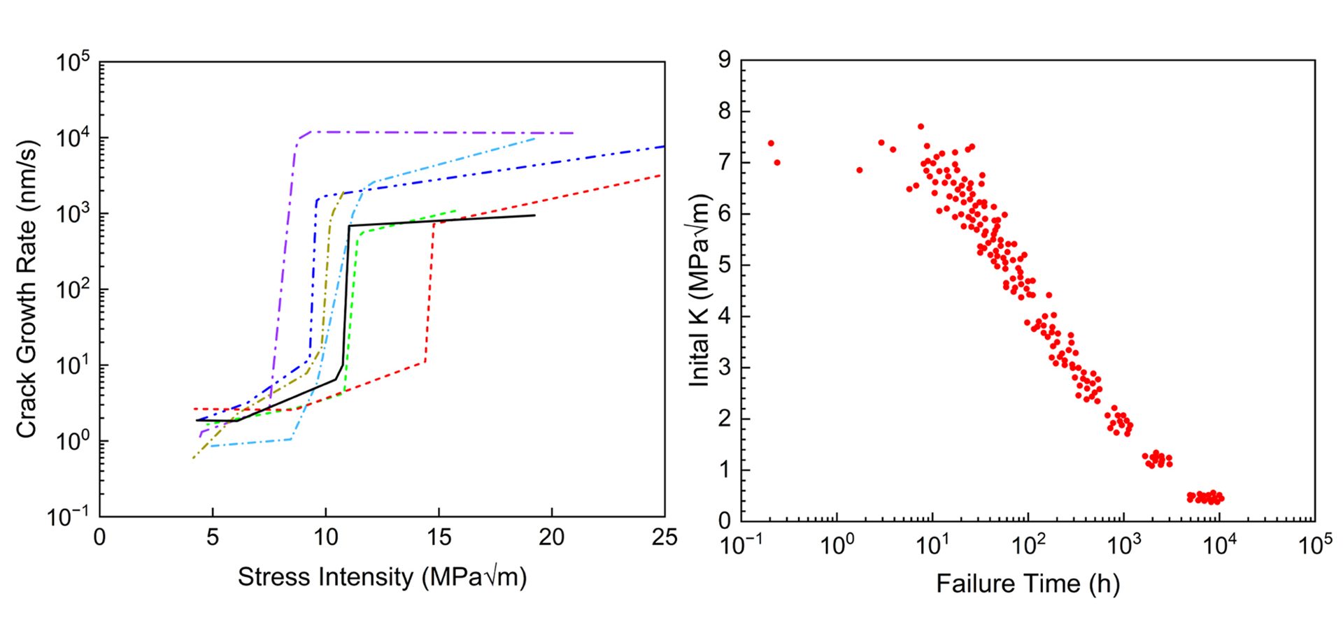
An example of this modelling technique is shown for a sensitised aluminium alloy (AA5083-H131) in salt water. Fig. 2a shows the modelled variability of the cracking kinetics based on experimental measurements. These serve as some of the input data for probabilistic model predictions of failure time, as shown in Fig. 2b. This example shows how the material variability may be accounted for, however variability in stress state, environment, or other input parameter could be addressed in a similar way. Such probabilistic predictions of the SCC behaviour could inform DSC risk management.
To extend this work to the conditions relevant to the DSC, the maximum pit values are being developed as a function of the various bulk environmental parameters and will be coupled with a probabilistic representation of different residual stress profiles19 and component geometry profiles to calculate the range of K-values using the Kondo approach. These values can be compared to the measured KISCC to quantitatively determine what conditions will cause sufficiently large pits to initiate SCC cracking. Furthermore, the bulk conditions used to develop the maximum pit size can be linked to DSC geolocation, thus enabling quantitative ranking of the relative risk at different geolocations. The parameters specific to DSC applications will be incorporated into the VEXTEC FM-based probabilistic software17 to enable prediction of the SCC crack growth over time using inputs of residual stress profiles, initial pit sizes, environment specific da/dt versus K relationships, and material conditions. The result will be probabilistic predictions of SCC at multiple individual component locations, providing an overall risk profile for the entire canister and can be extended to an inventory at an ISFSI.
Validation steps
Building on the validation of the maximum pit model for austenitic stainless steels in ferric chloride,8 similar testing will be done on SS304L and SS316L in DSC-relevant conditions. The time evolution of the pitting statistics (i.e., size distributions, maximum pit size) will be collected. The maximum pit size measured will be compared to model predictions. Sandia National Laboratories has the capability to process hundreds of samples and, in turn, develop statistically-relevant datasets on pit size and shape frequency distributions over time. From this, experimental data on observed maximum pit size, rmax(t), can be compared to model predictions. Isolated FM tests will be performed in environments with controlled pit and load configurations that lead to K values that are either below or above the measured KISCC. The results will be used to ensure that this approach captures the relevant rankings of pit severity and capture any quantitative errors from arising, assuming the pit is an FM flaw.
References
- EPRI. “Literature Review of Environmental Conditions and Chloride-Induced Degradation Relevant to Stainless Steel Canisters in Dry Cask Storage Systems.” 3002002528 (2014)
- Prosek, T, Iversen, A, Taxén, C & Thierry, D, Corros. Sci. 65, 105–117 (2009)
- Scheel, J E, Hornbach, D J & Prevey, P S, Proc. ICONE16 1–8 (2009)
- Stewart, J & Williams, D E, Corros. Sci. 33, 457–474 (1992)
- Williams, D E, Westcott, C & Fleischmann, M J, Electroanal. Chem. Interfacial Electrochem. 180, 549–564 (1984)
- Organ, L, Scully, J R, Mikhailov, A S & Hudson, J L, Electrochim. Acta 51, 225–241 (2005)
- Xie, Y, Zhang, J, Aldemir, T & Denning, R, Reliab. Eng. Syst. Saf. 172, 239–248 (2018)
- Woldemedhin, M T, Shedd, M E & Kelly, R G J, Electrochem. Soc. 161, 3216–3224 (2014)
- Chen, Z Y & Kelly, R G J, Electrochem. Soc. 157, C69 (2010)
- Chen, Z Y, Cui, F & Kelly, R G J, Electrochem. Soc. 155, C360 (2008)
- Albores-Silva, O E, Charles, E A & Padovani, C, Corros. Eng. Sci. Technol. 46, 124–129 (2011)
- Kondo, Y, Corros. Sci. 45, 7–11 (1989)
- Van Der Walde, K & Hillberry, B M, Int. J. Fatigue 29, 1269–1281 (2007)
- Burns, J T, Kim, S & Gangloff, R P, Corros. Sci. 52, 498–508 (2010)
- Shi, P & Mahadevan, S, Eng. Fract. Mech. 68, 1493–1507 (2001)
- McMahon, M E, Steiner, P J, Lass, A B & Burns, J T, Corros. Sci. 73, 713–723 (2017)
- Gangloff, R P, Corrosion 9312, 862–880 (2016)
- Steiner, P J & Burns, J T, Corros. Sci. 74, 1117–1131 (2018)
- Enos, D & Bryan, C, “FCRD-UFD-2016-000064.” Sandia Natl. Lab. (2016)