Dr Morris Kesler, Chief Technology Officer at WiTricity Corporation, discusses their highly resonant wireless power technology.
The idea of transmitting power through the air has been around for over a century, with Nikola Tesla’s ideas perhaps being the most well-known early attempts to do so1. Most approaches to wireless power transfer use an electromagnetic (EM) field of some frequency for transferring power. Lasers can transmit power via a collimated beam of light to a remote detector where the received photons are converted to electrical energy. Efficient transmission over large distances is possible with this approach.
However, complicated pointing and tracking mechanisms are needed to maintain proper alignment between moving transmitters and/or receivers. In addition, objects that get between the transmitter and receiver can block the beam, interrupting the power transmission and, depending on the power level, can possibly cause harm. At microwave frequencies, a similar approach can be used to efficiently transmit power over large distances using the radiated EM field from appropriately sized antennas.2 However, similar caveats about safety and system complexity apply to these radiative approaches.
It is also possible to transmit power using non-radiative fields. As an example, the operation of a transformer can be considered a form of wireless power transfer since it uses the principle of magnetic induction to transfer energy from a primary coil to a secondary coil without a direct electrical connection. However, for these systems to operate efficiently, the primary coil (source) and secondary coil (device) must be in close proximity and carefully positioned to one another.
But what about going over somewhat larger distances or having more freedom in positioning the source and device relative to each other? That is the question a group at the Massachusetts Institute of Technology (MIT) asked themselves. They explored many techniques for transmitting power over ‘mid-range’ distances and arrived at a non-radiative approach that uses resonance to enhance the efficiency of the energy transfer (see Physics of Highly Resonant Power Transfer for details).3,4,5,6
High-quality factor resonators enable efficient energy transfer at lower coupling rates, i.e., at greater distances and/or with more positional freedom than is otherwise possible. Because of this, this approach is sometimes referred to as ‘highly resonant’ wireless power transfer (HR-WPT). The MIT team demonstrated the highly resonant technique using a magnetic field to transfer energy over a distance of two metres, and an industry was born. In some instances, this technology is also referred to as ‘magnetic resonance’, often contrasted to ‘induction’ for its ability to efficiently transfer power over a range of distances and with positional and orientational offsets.
System description
Across an application space that spans power levels from less than a watt to multiple kilowatts, a wireless energy transfer system based on HR-WPT often has a common set of functional blocks. A general diagram of such a system is shown in Fig. 1.
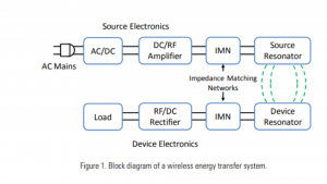
Progressing from left to right on the top line of the diagram, the system’s input power is usually either via wall power (AC mains) which is converted to DC in an AC/DC rectifier block, or a DC voltage directly from a battery or other DC supply. In high-power applications, a power factor correction stage may also be included in this block. A high-efficiency switching amplifier converts the DC voltage into an RF voltage waveform used to drive the source resonator. An impedance matching network (IMN) is often used to effectively couple the amplifier output to the source resonator while enabling efficient switching-amplifier operation. Class D or E switching amplifiers are suitable in many applications and generally require an inductive load impedance for the highest efficiency.
The IMN transforms the source resonator impedance, loaded by the coupling to the device resonator and output load, into such an impedance for the source amplifier. The magnetic field generated by the source resonator couples to the device resonator, exciting the resonator and causing energy build-up. This energy is coupled out of the device resonator to do valuable work, for example, directly powering a load or charging a battery. A second IMN may be used here to efficiently couple energy from the resonator to the load. It may transform the actual load impedance into an effective load impedance seen by the device resonator, closely matching the loading for optimum efficiency (Equation 5). For loads requiring a DC voltage, a rectifier converts the received AC power back into DC.
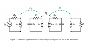
In the earliest work at MIT, the impedance matching was accomplished by inductively coupling into the source resonator and out of the device resonator.3 This approach provides a way to tune the input coupling and, therefore, the input impedance by adjusting the alignment between the source input coupling coil and the source resonator. Similarly, the approach also provides a way to tune the output coupling and, therefore, the effective loading on the device resonator. It does this by adjusting the alignment between the device output coupling coil and the device resonator.
With proper adjustment of the coupling values, it was possible to achieve power transfer efficiencies approaching the optimum possible efficiency (Equation 6). Fig. 2 shows a schematic representation of an inductive coupling approach to impedance matching. In this circuit Mg is adjusted to provide the desired input impedance for the given loading of the source resonator. The device resonator is similarly loaded by adjusting ML, the mutual coupling to the load. Series capacitors may be needed in the input and output coupling coils to improve efficiency unless the reactances of the coupling inductors are much less than the generator and load resistances.
It is also possible to directly connect the generator and load to the respective resonators with various IMNs. These generally comprise components (capacitors and inductors) arranged in ‘T’ and/or ‘pi’ configurations. The values of these components may be chosen for optimum efficiency at a specific source-to-device coupling and load condition (‘fixed tuned’ impedance matching), or they may be adjustable to provide higher performance over a range of source-to-device positions and load conditions (‘tunable’ impedance matching). Requirements of the particular application will determine which approach is most appropriate from a performance and cost perspective.
The efficiency of wireless charging is often questioned. The end-to-end efficiency of a wireless energy transfer system is the product of the wireless efficiency and the efficiency of the electronics (RF amplifier, rectifier, and any other power conversion stages, if needed). In high-power applications, such as charging electric vehicles (EVs) at multi-kilowatt levels, end-to-end efficiencies (AC input to DC output) greater than 94% have been demonstrated.
People often do not believe that magnetic resonance could be as efficient as the familiar plug-in charging for EVs. However, the block diagram for a plug-in charger is similar to that of a wireless charger. The wireless portion, i.e., the source and device resonators, is replaced by a transformer. The other power electronics components are similar, so the efficiency of a well-designed wireless charger is on par with conventional plug-in chargers.
Physics of highly resonant wireless power transfer
Resonance
In general, resonance involves energy oscillating between two modes. In a system at resonance, it is possible to have a significant build-up of stored energy while having only a weak excitation to the system. The build-up occurs if the energy injection rate into the system is greater than the rate of energy loss by the system.
The characteristics of an isolated resonator can be described by two fundamental parameters; its resonant frequency ω0 and its intrinsic loss rate, Γ. The ratio of these two parameters defines the quality factor or Q of the resonator, [Q=ω0/(2Γ)] a measure of how well it stores energy. An example of an electromagnetic resonator is the circuit shown in Fig. 3, containing an inductor, a capacitor, and a resistor.
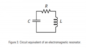
In this circuit, energy oscillates at the resonant frequency between the inductor (energy stored in the magnetic field) and the capacitor (energy stored in the electric field) and is dissipated in the resistor. The resonant frequency and the quality factor for this resonator are:
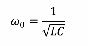
and
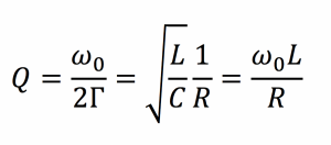
The expression for Q shows that decreasing the loss in the circuit, i.e., reducing R, increases the quality factor of the system.
In highly resonant wireless power transfer systems, the system resonators must have a high-quality factor to efficiently transfer energy. High-Q electromagnetic resonators are typically made from conductors and components with low absorptive (also sometimes referred to as ohmic, resistive, series resistive, etc.) losses, exhibit low radiative losses, and as a result, have relatively narrow resonant frequency widths. Also, the resonators may be designed to reduce their interactions with extraneous objects, which may cause loss.
Coupled resonators
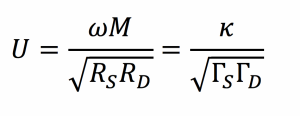
If two resonators are placed in proximity to one another such that there is coupling between them, it becomes possible for the resonators to exchange energy. The efficiency of the energy exchange depends on the characteristic parameters for each resonator and the energy coupling rate, κ, between them. The dynamics of the two-resonator system can be described using coupled-mode theory,3 or from an analysis of a circuit equivalent of the coupled system of resonators.
One equivalent circuit for coupled resonators is the series resonant circuit shown in Fig. 4.
Here the generator is a sinusoidal voltage source with amplitude Vg at frequency ω with equivalent generator resistance Rg. The source and device resonator coils are represented by the inductors LS and LD, which are coupled through the mutual inductance M, where M=k√(LS LD ). Each coil has a capacitor to form a resonator. The resistances RS and RD are the parasitic resistances (including both ohmic and radiative losses) of the coil and resonant capacitor for the respective resonators. The load is represented by an equivalent AC resistance RL.
Analysis of this circuit gives the power delivered to the load resistor, divided by the maximum power available from the source when both the source and device are resonant at ω as:
where
We can choose the generator and load resistances that give the best system performance (or use an impedance transformation network to match other resistance values). If we select
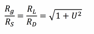
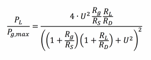
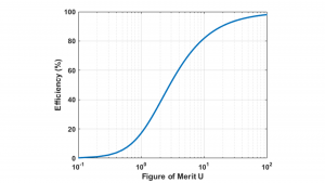
then the efficiency of the power transmission as defined above is maximised and is given by

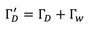
and shown in Fig. 5. Here, highly efficient energy transfer is possible in systems with large values of U. Note that the impedance matching described above is equivalent to the coupled-mode theory treatment that shows work extracted from a device can be modelled as a circuit resistance that has the effect of contributing an additional term, Γw, to an unloaded device object’s energy loss rate ΓD, so that the overall energy loss rate is given by
and that the efficiency of the power transmission is maximised when
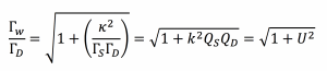
Note that the best possible efficiency of a wireless power transmission system only depends on the system figure-of-merit, which can also be written in terms of the magnetic coupling coefficient between the resonators, k, and the unloaded resonator quality factors, QS and QD.
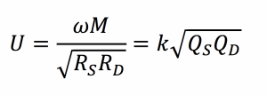
Knowing the resonator quality factors and the range of magnetic coupling between them for a specific application, one can use Equations 6 and 9 to determine the best efficiency possible for the system.
The analysis above illustrates the importance of the coupling and resonator quality factor for wireless power technology using magnetic resonance. The magnetic coupling coefficient is a dimensionless parameter representing the fraction of magnetic flux that is coupled between the source and device resonators, and has a magnitude between zero (no coupling) and one (all flux is coupled). Coupling is a function of the relative sizes of the resonators, the distance between them, and their relative orientation. Wireless power technology transmission systems based on traditional induction (e.g., cordless toothbrushes) are typically designed for larger values of coupling and, as a result, require close spacing and precise alignment between source and device. Equations 6 and 9 show that using high-quality resonators allows for efficient operation even at lower coupling values, eliminating the need for precise positioning between source and device and providing greater freedom of movement. The ability to achieve high efficiency even at low coupling factors expands the application space for wireless power far beyond that of traditional induction.
Human safety considerations
The safety of wireless power technology using magnetic resonance systems often comes into question. Perhaps because these systems can efficiently exchange energy over mid-range distances, people may assume they are being exposed to large and potentially dangerous electromagnetic fields when using these systems.
Of course, WiTricity’s wireless power technology is not ‘electricity-in-the-air’ but rather a technology that uses oscillating magnetic fields to mediate the wireless energy exchange. With proper design, the stray electric and magnetic fields can be kept below the well-established and long-standing human safety limits that regulate all electromagnetic consumer devices, including mobile phones, wireless routers, Bluetooth headphones, radio transmitters, etc. At WiTricity, we perform a detailed electromagnetic analysis, ensuring that the systems meet all applicable human safety guidelines.
The future of wireless power transfer
With a maturing technology base and a broad application space, wireless power transfer will become prevalent in many areas of life in the coming years. Since the original demonstrations at MIT early this century, magnetic resonance technology has moved from a scientific experiment to the production line, where it is now being incorporated into mass-produced autonomous factory robotics and other industrial devices, drones, and e-mobility devices. Even more exciting, EVs, both plug-in hybrids and full battery EVs, are now shipping with factory-installed wireless charging. Worldwide standards for wireless power technology in all these application areas have been developed to ensure interoperability across products and brands, facilitate the deployment of wireless charging infrastructure, and help to accelerate the adoption of the technology.
Some advanced automotive technology, will benefit significantly from the ability to charge without human intervention. Wireless charging is almost essential for deploying autonomous vehicles where there may not be anyone around to connect a wired charger (or otherwise add fuel). Research into dynamic charging of vehicles, using the same basic magnetic resonance technology, is underway and was demonstrated by Qualcomm’s Halo team in 2017, now a part of WiTricity.
Of course, there will likely be applications for wireless power that we cannot envision today. With the pace of technology innovation, expect to see wireless power technology deployed not only in the areas mentioned here but in many more applications.
References
1. Nicola Tesla, “The transmission of electrical energy without wires”, Electrical World and Engineer, March 1905. http://www.tfcbooks.com/tesla/1904-03-05.htm, (acc. Dec. 08)
2. William C. Brown, “The history of power transmission by radio waves”, Microwave Theory and Techniques, IEEE Transactions, 32(9):1230-1242, September 1984.
3. A.B. Kurs, A. Karalis, R. Moffatt, J.D. Joannopoulos, P.H. Fisher, and M. Soljacic, “Wireless Power Transfer via Strongly Coupled Magnetic Resonances”, Science, 317, pp. 83-86, (2007).
4. A. Karalis, J.D. Joannopoulos, and M. Soljacic, “Efficient Wireless Non-radiative Mid-range Energy Transfer”, Ann. Phys., 323, pp. 34-48, (2008) published online April 2007.
5. J.D. Joannopoulos, A. Karalis, and M. Soljacic, “Wireless Non-Radiative Energy Transfer”, US Patent Numbers 7,741,734; 8,022,576; 8,084,889; and 8,076,800.
6 A. Karalis, A.B. Kurs, R. Moffatt, J.D. Joannopoulos, P.H. Fisher, and M. Soljacic, “Wireless Energy Transfer”, US Patent Numbers 7,825,543 and 8,097,093.
Please note, this article will also appear in the eighth edition of our quarterly publication.