Professor James F Stubbins from the University of Illinois Urbana-Champaign details how technology is allowing us to ‘look inside’ irradiated steels to determine the durability of a nuclear structure.
One of the founding principles in materials science is that the internal microstructure of a material controls the material performance. Because of this, there has always been an intense interest in studying and classifying the internal structures in materials as a means of understanding and predicting their performance. Most of this work has been aided by the continuing and rapidly advancing development of microstructural analysis techniques to probe smaller and smaller regions of the material structure, down to the atomistic level.
The atomistic level information is critical to understand the internal changes in the material. However, the major challenge is to link that understanding to the performance of realistic-scale materials structures. We have been interested in building, on the atomistic level, information to understand how actual structures behave under real-life application conditions – can we understand the durability of a structure from our atomistic-level materials characterisation?
Irradiated steel in nuclear applications
Irradiated steel structures have long been used for building nuclear systems and are a high priority for applications in the next generation of advanced nuclear reactor systems. For advanced nuclear systems, steels with compositions of Fe-9 to 12Cr have attracted the most interest and the largest levels of experimental and modelling activities. These types of irradiated steel have been used in advanced nuclear systems and are of high interest for future systems because they are resistant to the internal damage caused by irradiation. Exposure to intense irradiation fields inside a nuclear reactor can drastically change the material’s mechanical properties and can alter the material’s physical dimensions. Finding materials that can resist these changes is essential for reactor life cycles and safety.
Here, we describe experimental discoveries on Fe-9 to 12 Cr model and commercial steel alloys to show what happens inside irradiated steel when it is subjected to intense irradiation fields at elevated temperatures inside an operating nuclear reactor. Our materials were irradiated in the Advanced Test Reactor (ATR) at Idaho National Laboratory (INL). They were subjected to neutron irradiations up to 10 displacements per atom (dpa). The figure of merit for radiation damage, dpa, indicates how many times on average each atom in the material has been knocked out of its normal position into another location in the material. 10 dpa indicates that every atom in the material has been knocked or displaced from its starting position to another location ten times during the irradiation exposure. So, on average, all of the atoms in the material are not in the same positions where they started. Many of them fall back into normal positions in the material’s crystal lattice, but some move around and combine with other ‘displaced’ atoms to form ‘defects’ or clusters that are different from the starting structure.
Investigating irradiation damage
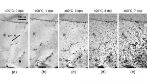
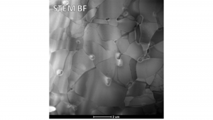
It is possible to watch the evolution of defect clusters in irradiated steel. Using high-energy ion beams directed into a transmission electron microscope stimulates the damage found in nuclear reactors. This technique provides a clear picture of the ways in which small defect clusters form and grow with irradiation damage. The small ‘black’ dots that form with irradiation exposure, shown in Fig. 1, are small clusters of atoms that have been ‘displaced’ and moved together to form small clusters. These clusters act as a strengthening agent to make the material stronger, but they also tend to make the material more brittle.
The irradiation damage structures shown in Fig. 1 are an indication of what can happen when irradiating a small, thin slice of material. For real reactor conditions, it is beneficial to look at materials that have been irradiated in an operating reactor. We have been examining these types of materials, such as irradiated steel, that have been irradiated inside the ATR at INL. The ATR is a facility where large volumes of experimental materials can be irradiated to damage levels of interest for current and advanced nuclear energy systems.

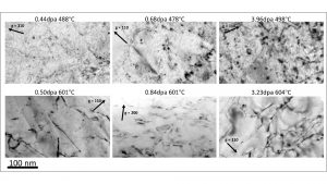
In Fig. 3, we show the same commercial steel, T91 (Fe-9Cr-1Mo), from Fig. 1 after irradiation exposure in ATR over three dose levels at two temperatures. The defect structures in the top row are similar to those found in Fig. 1. At higher temperatures, the defect structures develop more rapidly, indicating that irradiation temperature is also an important element determining a material’s performance.
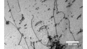
We have also looked at model alloys with simpler compositions. For example, Fig. 4 shows a Fe-10Cr model irradiated steel. Some of the radiation defects are similar to the T91 alloy, but there are also some larger defect structures which come about due to the simpler composition in this model irradiated steel. Part of the reason for these larger ‘loop’ structures is that the additional alloying elements in the T91 steels tend to retard the growth of the large ‘loop’ structures at low dpa doses.
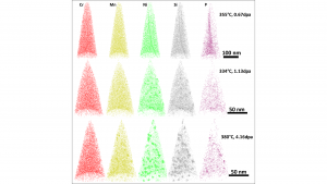
The consequences of the additional alloying elements in the T91 steel compared to the simpler Fe-9 or 10Cr steel can be seen by looking at the ways in which the other alloying elements behave and move around during irradiation. In many cases, the minor alloying elements form their own cluster types, which can have deleterious effects on the irradiated steel’s performance. The best way to look at the clustering of various elements in the irradiated steels is by using Atom Probe Tomography (APT), where the atoms on the tip of a ‘needle’ are stripped away layer by layer and characterised by which type of atoms they are. An example of this is shown for HT9, a Fe-12Cr commercial alloy, in Fig. 5, where Mn, Ni, Si, and P segregate during irradiation to form a specific type of defect cluster. The small defect clusters of Mn-Ni-Si and some P can be seen to develop as the irradiation dose increases. These clusters grow into a new phase, the G-phase, with a composition of Ni16Mn6Si7 which can also have deleterious effects on the performance of the steel.
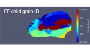
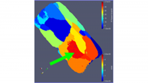
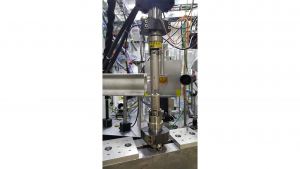
These microstructural features from transmission electron microscopy and atom probe tomography are very helpful in understanding how the ‘inside’ of the steels change during irradiation damage as a function of irradiation dose and temperature. We are also interested in understanding how these internal changes to the material’s microstructure affect the material’s mechanical properties. Realistic mechanical properties must be measured on a much larger scale than microstructural measurements. To examine those effects, we have been employing high-energy X-rays to also look inside the material as it is subjected to stress or mechanical loading. This research has been performed at the Advanced Photon Source (APS) at Argonne National Laboratory. Using a synchrotron source with high-energy X-rays, we are able to ‘watch’ the irradiated steel as it deforms under applied stress. Using a combination of near-field and far-field diffraction information, it is possible to reconstruct both the material’s internal structure and the crystallographic information about each internal ‘grain.’ In the images above, we typically look at one part of a grain or specific crystal section at a time. For the APS work, we are able to look at many grains or individual crystals to see their co-operative behaviour when they are deformed. This provides a more realistic picture of how they will behave in a real application.
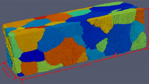
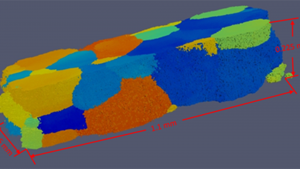
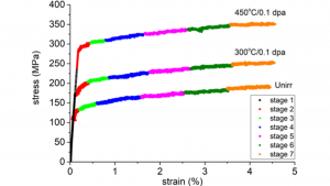
The irradiation damage structures for the Fe-10Cr alloy were shown in Fig. 4. We have looked at the deformation behaviour of the same model alloy Fe-10Cr during tensile loading. In Fig. 6, the structures and orientations of various grains in the unirradiated Fe-9Cr system are shown. By comparing the grain shapes, it is possible to see the amount of change in the grain shapes due to loading the material beyond the yield point, so there is some residual permanent, plastic deformation. An important point is that all of the grains need to deform together to accommodate the deformation in their neighbouring grains. This provides a full picture of the behaviour of a large section of material during deformation.
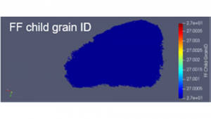
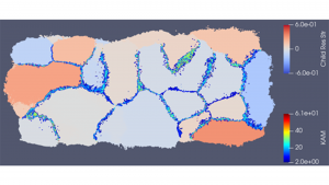
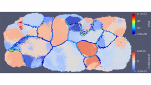
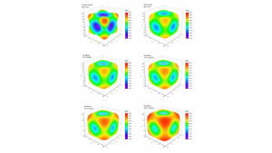
Because of the ability to identify various grains, their orientations, and their neighbouring grains, it is possible to pick out individual grains to determine the extent of their internal deformation. Fig. 7 compares the changes in internal strain in a single grain due to its deformation and the impact of the surrounding grains on its loading response.
These results allow us to determine the controlling deformation mechanism of irradiated versus unirradiated Fr-9-12Cr steels. Since we can look inside the deforming irradiated steel and separate out individual grains and their response to the loading and their surrounding neighbourhood, we can determine how they will behave under loading conditions inside an operating nuclear reactor.
The Fe-Cr alloy described above does not contain significant carbon. Carbon is a major additive component in this alloy system to provide strength. The strengthening comes from the formation of internal carbides as the carbon combines with either Cr or Fe to form (Cr,Fe)23C6 (usually M23C6 where M stands for metal and is either Cr or Fe or both) or other possible carbides. During loading, the carbides, which are extremely strong and barriers to deformation, provide strengthening. For Fe-9Cr-C model alloys, we have looked at the behaviour of the carbides during loading to take up their ‘share’ of the load. This research also employs the Advanced Photon System at Argonne National Laboratory to determine how the carbides in the steel ‘share’ the load when the steel is put under stress. This load sharing is one of the major ways that carbides strengthen irradiated steel.
The experimental results show us that the M23C6 carbides have elastic strength properties that depend on their crystal orientation. By examining their loading characteristics from a single crystal to multicrystals and various M23C6 content, we find that, despite the strong directionality in strength (single crystal), the M23C6 contributions to strengthening of the steels are much more uniform in multi-crystalline structures where their orientations are randomly oriented. However, at very high levels of internal carbides, their strong influence on directional differences in strength returns. For realistic systems, the 4% of M23C6 in the Fe-9Cr-0.1C matrix is typical.
The response of materials to exposure to high levels of irradiation has been a major topic of interest since the dawn of the nuclear age. For much of that time, technologies to analyse changes in materials’ microstructures have been applied successfully to image radiation-induced defects. Post-irradiation examination (PIE) has been used for testing materials. The development of transmission electron microscopy over the past 50 years has provided new insights, and atom probe tomography has provided a resolution at the atomic level. Transmission electron microscopy usually examines volumes of irradiated materials on the order of 10-19 to 10-20m3, while atom probe tomography examines even smaller volumes of materials at about 10-21m3. These represent very small materials volumes which may not capture the full extent of the effects of irradiation on materials performance. We have demonstrated in recent research that the use of synchrotron sources can probe materials volumes on the order of 10-9m3, or orders of magnitude larger volumes. This enables the possibilities to examine and characterise the effects of irradiation damage ‘inside’ nuclear reactor irradiated materials at an important scale for realistic applications. This approach has provided a new window into materials performance with real-world implications for nuclear materials development and applications. This technology has really allowed us to ‘look inside’ irradiated steels.

Acknowledgements
The experimental work described here has been accomplished at major U.S. Department of Energy (DOE) scientific user facilities, with the help of their excellent technical and scientific staff. These include the Nuclear Science User Facilities (NSUF): the Advanced Test Reactor, the Center for Advanced Energy Studies – Microscopy and Characterization Suite, the Hot Fuels Examination Facility at Idaho National Laboratory, and the IVEM-Tandem facility at Argonne National Laboratory. The high-power X-ray experiments were performed at the Advanced Photon Source at Argonne National Laboratory. The support of DOE, NRC and NNSA of the research team was also critical for this research.
References
- Liu, X., Miao, Y., Li, M., Kirk, M., Maloy, S.A., Stubbins, J. F., “Ion-irradiation-induced microstructural modifications in ferritic/martensitic steel T91,” Journal of Nuclear Materials, V. 490 pp 305-315 (Jul 2017). DOI: 10.1016/j.jnucmat.2017.04.047
- Huan Yan, Xiang Chen, Lingfeng He, James Stubbins, “Early-stage microstructural evolution and phase stability in neutron-irradiated ferritic/martensitic T91, under review, Journal of Nuclear Materials, 557 (Dec 2021) 153207
- Huan Yan, Xiang Chen, Lingfeng He, James Stubbins, “Phase stability and microstructural evolution in neutron-irradiated ferritic/martensitic HT9, Journal of Nuclear Materials, 557 (Dec 2021) 153252 https://doi.org/10.1016/j.jnucmat.2021.153252
- Chen, W., Miao, Y., Wu, Y., Tomchik, C., Mo, K., Gan, J., Okuniewski, M., Maloy, S., and J.F. Stubbins, “Atom probe study of irradiation-enhanced α′ precipitation in neutron-irradiated Fe–Cr model alloys,” Journal of Nuclear Materials, V. 462, pp 242-249 (2014)
- Chen, W.-Y., Miao, Y., Wu, Y., Tomchik, C., Mo, K., Gan, J., Okuniewski, M., Maloy, S., J.F. Stubbins, “Atom probe study of irradiation-enhanced α′ precipitation in neutron-irradiated Fe–Cr model alloys,” Journal of Nuclear Materials, V. 462, pp 242-249 (Jul 2015)
- Chen, W.-Y., Miao, Y., Wu, Y., Tomchik, C., Mo, K., Gan, J., Okuniewski, M., Maloy, S., J.F. Stubbins, Corrigendum to “Atom probe study of irradiation-enhanced alpha′ precipitation in neutron-irradiated Fe–Cr model alloys” [Journal of Nuclear Materials, V. 462 (2015) 242–249], Journal of Nuclear Materials, V. 467, pp 392-392 part: 1, (Dec 2015)
- Chen, W., Y., Miao, Y., B., Gan, J., Okuniewski, M., A., Maloy, S., A., Stubbins, J. F., “Neutron Irradiation Effects in Fe and Fe-Cr at 300°C,” Acta Materialia, V. 111 pp 407-416 (Jun 2016)
- Zhang, X., Li, Meimei, Park, J.S., Kenesei, P., Almer, J., Xu, C., Stubbins, J. F., “In situ high-energy X-ray diffraction study of tensile deformation of neutron-irradiated polycrystalline Fe-9%Cr alloy,” Acta Materialia V. 126 pp 67-76 (Mar 2017)
- Xuan Zhang, Meimei Li, Jun-Sang Park, Peter Kenesei, Hemant Sharma, Jonathan Almer, High-energy x-ray diffraction microscopy study of deformation microstructures in neutron-irradiated polycrystalline Fe-9%Cr, Journal of Nuclear Materials, 508 556-566 (2018). https://doi.org/10.1016/j.jnucmat.2018.06.004
- Dominic Piedmont, Xuan Zhang, …. J. Stubbins (in progress)
- Hoon Lee, J. Stubbins, … (in progress)
Please note, this article will also appear in the fourteenth edition of our quarterly publication.