Dr Carlos Ziebert, Head of IAM-AWP’s Calorimeter Center, KIT, answers frequently asked questions regarding battery safety and explains how it can be improved by battery calorimetry.
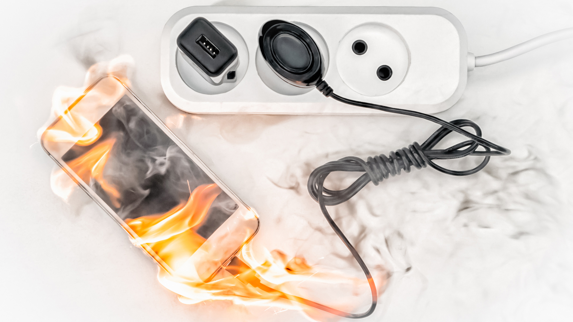
Everyone is familiar with the pictures of burning mobile phones, notebooks or even electric vehicles, such as e-bikes, electric cars and buses (as well as house fires) from the media (see Fig. 1 and 2). Many of these events can be traced back to a critical failure of lithium-ion batteries (LIBs), which are their power source. This has led to a more or less factual discussion in recent years, which ultimately led to uncertainty among (potential) customers worldwide. These customers have developed reservations about the use of ‘equipment’ that uses LIBs.
It is clear that safety issues have a significant influence on consumers’ willingness to adopt new technologies. It is well known that in comparison to other battery types such as nickel-metal hydride or lead-acid batteries, LIBs have the advantages of a high specific energy, long cycle life, and low self-discharge rates. However, battery accidents have raised concerns and have hindered the rapid market penetration of electric vehicles, for example. Therefore, it is helpful to ask and answer several important questions.
What causes a thermal runaway in a battery?
A safety risk arises when a permissible upper limit for the temperature of a cell is exceeded. If this is the case, exothermic reactions occur, resulting in an increase in temperature, which in turn triggers further reactions. If the dissipated heat is too low or the heat supply is too great, a heating-reaction cycle is created, characterised by the term ‘thermal runaway’.
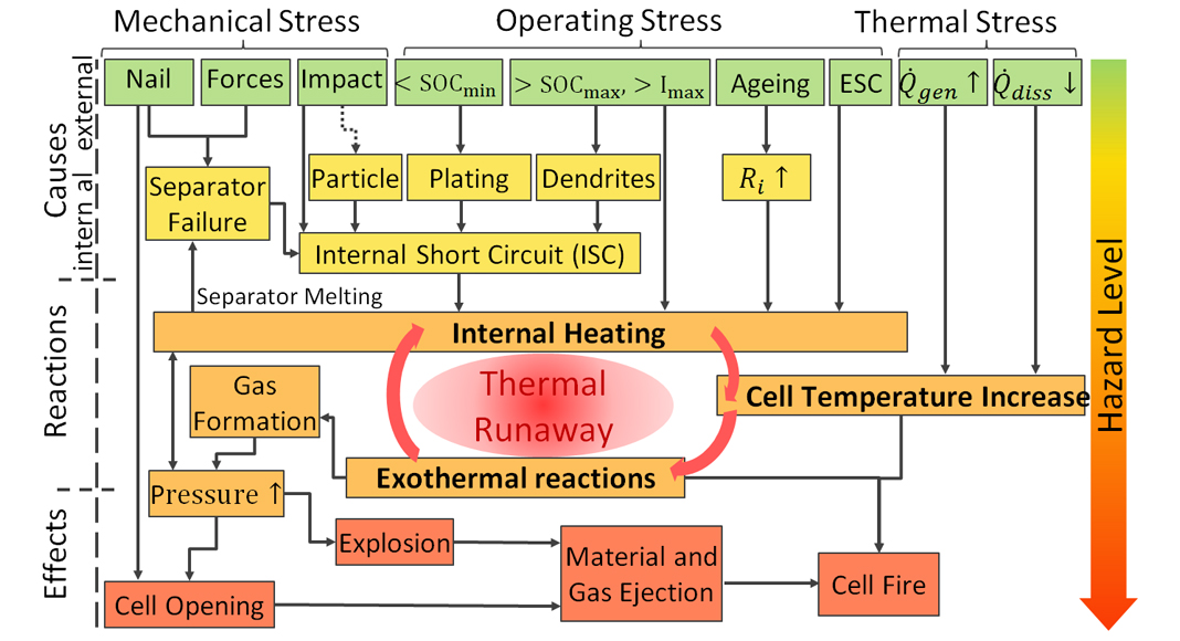
The literature does not clearly define the temperature rates from which one can speak of a thermal runaway. Our measurements show that the cell usually goes into thermal runaway from temperature rates of 10-60 K min-1. The fact that the chemical energy is about eight times that of the electrically stored energy illustrates the risk of such an uncontrolled release of this energy. The causes and effects of thermal runaway can be very diverse and complex (Fig. 3). A thermal runaway is preceded by an unusually high-temperature rise that requires a trigger.
The causes can be internal as well as external:
- Internal short circuit caused by dendrite formation; particle migration (copper, metal particle residue, or separator failure (high temperature, faulty production);
- External short circuit;
- Overcharging or deep discharge and very large current;
- Mechanical effects including vibration/shock, squeezing, nail penetration;
- Strong temperature increase in the environment; and
- Insufficient or defective cooling.
These lead to internal heating of the cell that initiates different exothermal reactions shown in Fig. 4, followed by a further temperature and pressure increase. Typically, the first reactions are the decomposition of the solid-electrolyte interphase (SEI) layer, which is formed during the formation process of the cell and protects the anode and cathode from the electrolyte. The second stage consists of reactions of the electrode binder material with the released Li or the melting of the polymer components of the separator materials that prevent a short circuit. Then the third stage is the decomposition of the electrolyte and the electrodes with rapid oxygen generation that end up in the thermal runaway.

The final effects can be empirically classified by the Hazard Level (1-7) as shown in Table 1, with 7 representing the highest level with explosive disintegration of the cell. Cell designs, component integrity, manufacturing, and ageing processes all have a critical influence on the safety of LIBs. Therefore, a holistic safety assessment is a prerequisite for upscaling and market acceptance of LIBs. This includes both safety measures and safety testing according to the relevant safety standards from materials, to components, to cell, up to module and pack level.
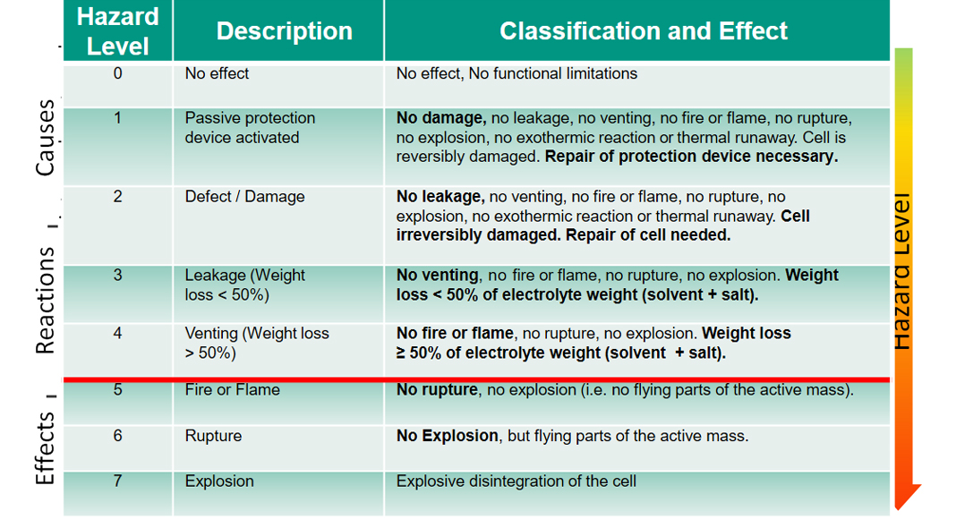
Fig. 3 also shows that the cycle of the thermal runaway can be interrupted by actively cooling the cell temperature so that the greatest risk level is prevented. Striving for a high energy density and high performance has a major impact on the hazard potential. An increase in energy and power usually leads to a deterioration in safety. In the event of a fault, more energy can be released in the same space or with the same mass so that the temperature rises faster.
What Battery Safety Technologies are currently used?
Avoiding a failure can be implemented on several levels. If the protection fails on one level, it can still be maintained on the next higher level. The levels are structured as follows: Component → Cell → Module → Battery system → Vehicle/device/building. Protective barriers can be set up between the levels to break the chain, for example, the isolation of individual cells or the metal housing around a battery in an electric vehicle. The possibilities are most diverse at the component and cell level.
On the component level, any safety-enhancing measure can interrupt or alleviate the thermal runaway. Improving the anode can mean that a trigger for the exothermic reactions is no longer applicable. Stabilising the cathode can increase the start temperature of exothermic reactions so that the exothermic cycle (see Fig. 3) is interrupted. This also applies to the stabilisation of the separator by ceramic alumina or zirconia coatings. Flame-retardant additives and a non-flammable electrolyte can prevent a cell fire and thus significantly reduce the intensity of a thermal failure.
On the cell level as an established safety device, the melting fuse takes effect very quickly if the currents are too high. However, after intervention and destruction, they must be replaced. Protection against overcharging by an overcharge safety device (OSD) is ensured by a membrane that bulges upwards when there is overpressure in the cell and short-circuits the charging current externally. The cell is no longer charged.
The protection against nail penetration (NSD) and impacts (CSD) causes a controlled internal short circuit with far less heat generation than without the protective device. OSD, NSD and CSD are used, for example, in Samsung hard case cells. If other safety measures remain ineffective, the safety vent serves as a backup for a cell that is already heating up and gassing. Even greater damage is prevented by the ejection of organic components and gases. The battery system must ensure the safe collection or discharge of the ejected material and the gases.
Are there tests to ensure the safe use of LIBs?
Safety tests are important at all levels. The single cell can be safe, but it can fail thermally in combination with several cells in a battery. Many internationally binding tests exist that cells or batteries have to pass, e.g. for air traffic and other transport routes. Every cell that is to be transported must pass the UN 38.3 test. This test consists of various pass and fail tests covering multiple relevant scenarios during transport, such as low air pressure during air transport, vibrations, strong temperature changes, mechanical shock, or external short circuits.
The topic is given top priority internationally. It is well-known that the failure of LIBs can be caused by mechanical abuse, electrical abuse, and thermal abuse, which have been compiled in the relevant safety testing standards, such as UN 38.3, SAE-J2464, IEC-62133, GB/T 31485 and UN GTR100.2. Thus, if these tests are correctly done, the safety can be guaranteed up to an acceptable level.
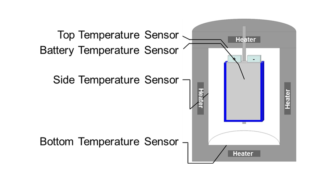
A very important device that is used more and more frequently for dedicated safety tests on LIBs is the accelerating rate calorimeter, whose working principle is shown in Fig.5. These robust battery calorimeters allow the evaluation of thermodynamic, thermal and safety data for LIBs under quasiadiabatic and isoperibolic environments for both normal and abuse conditions (thermal, electrical, and mechanical). The cell is inserted into the calorimeter chamber, which has heaters and thermocouples located in the lid, bottom and sidewalls that adjust the required ambient conditions that are characterised by the related thermocouples.
What are the benefits of Battery Calorimetry?
Calorimetry – or the process of measuring heat data during chemical reactions – allows the collection of the quantitative data required for optimum battery performance and safety. Sophisticated battery calorimetry can identify new and quantitative correlations between different critical safety and thermally related parameters. This is very important because you need to know how many Watts a cell will produce under every condition to adapt the battery and thermal management systems. The temperature, heat and internal pressure evolution can be studied while operating cells under conditions of normal use, abuse, or accidents. Especially, abuse tests without a calorimeter have two main disadvantages:
- The maximum safe temperature would be underestimated; and
- The consequences would be understated in terms of severity and speed.
Moreover, a test in a calorimeter is much more sensitive than a hotbox test and reveals the entire process of the thermal runaway with the different stages of exothermic reactions. These data are essential for battery and thermal management as well as safety system design. Combined with multiscale electrochemical-thermal modelling, they provide a powerful tool for thermal runaway prevention and ageing prediction.
Calorimeters allow a holistic safety assessment on:
- Materials level
On materials and components level, differential scanning calorimetry (DSC) and extremely sensible Tian-Calvet calorimeters can be used to provide thermophysical parameters such as heat capacity or thermal conductivity and to analyse in detail the possible phase transformations and the thermal stability of new battery materials. - Small-scale cell level
On small-scale cell level, isothermal and larger-scale Tian-Calvet calorimeters from Setaram Instrumentation allow the determination of the heat generation during cycling with great accuracy.
Using such calorimeters, 21700 format cylindrical cells with a maximum capacity of 5 Ah that are currently used, e.g. in the Tesla Model 3, can be studied. However, such calorimeters are not designed to withstand the high temperatures and even explosions that can occur during a thermal runaway.
- Large-scale cell level
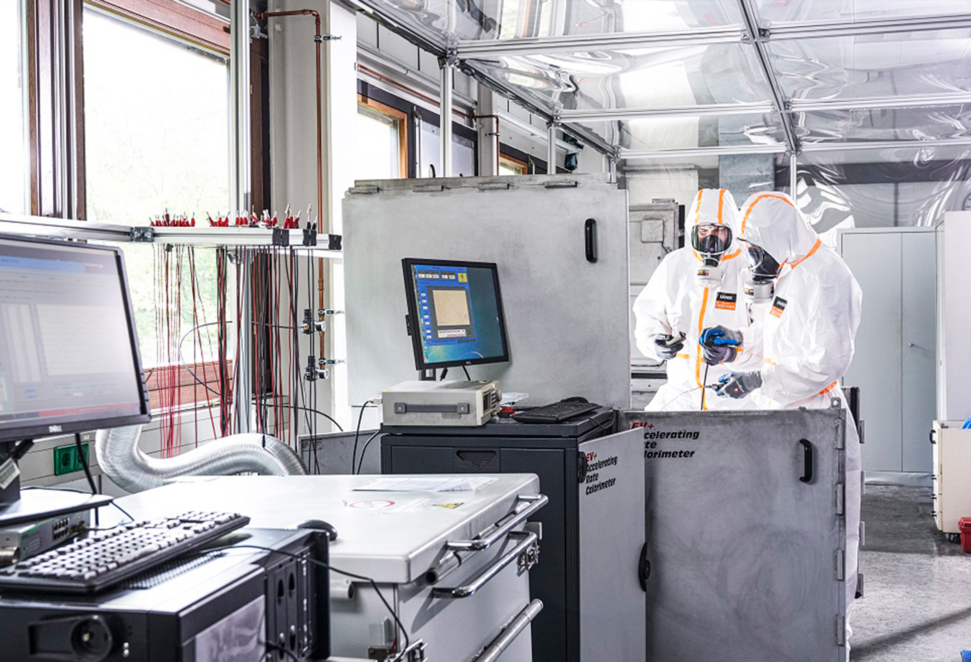
Therefore, the next level is robust adiabatic Accelerating Rate Calorimeters (ARCs). Nowadays, these are available from different manufacturers in different sizes – from coin to large pouch or prismatic automotive format and allow the evaluation of thermodynamic, thermal and safety data for lithium-ion cells on material, cell and pack level for both normal and abuse conditions (thermal, electrical, mechanical). The IAM-AWP Calorimeter Center that was funded in 2011 and currently operates Europe’s largest Battery Calorimeter Laboratory provides six ARCs from Thermal Hazard Technology of different sizes – from coin to 35cm x 30cm large automotive pouch or prismatic format with capacities of up to 150 Ah (Fig. 6, Fig. 7). - Small-scale pack level
As described in more detail in an article in The Innovation Platform, edition 4, the largest available ARC allows for the study of the thermal propagation in small-scale packs to develop and qualify suitable countermeasures, such as heat protection barriers1. Thermal propagation means that the thermal runaway propagates from one cell to the neighbouring cells, and this cascading effect can lead to the complete destruction of the module or pack.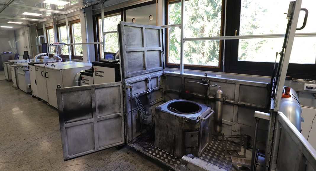
Fig. 6: IAM-AWP Battery Calorimeter Laboratory with six Accelerating Rate Calorimeters of different sizes
What safety testing can be performed in Battery Calorimeters?
The following three types of safety tests can be performed in the ARCs on cells for electric vehicle applications:
- Mechanical abuse: nail and crush test
When an applied force deforms the electric vehicle battery, mechanical abuse occurs. One cause is car crashes and puncturing the battery in the bottom of a chassis by a sharp object, which can also cause such deformation. This is simulated in the ARC by pushing a nail or a blunt object into the cell, which provides a pass/fail type test to qualify cells and quantitative data by measuring the cell temperature, cell voltage, and evolved heat. The mechanical abuse often causes an internal short circuit because the battery’s separator is damaged or punctured. - Electrical abuse: external/internal short circuit test, overcharge test, over-discharge test
Electrical abuse means the abnormal operation of electrical components, such as short circuiting, overcharging, and over-discharging. Typically, electrical abuse is related to a failure of the battery management system. However, the trend to fast charging might increase the risk of thermal runaway because it can lead to the deposition of highly reactive lithium on the carbon anode, the so-called lithium plating. The reason for that effect is that the lithium ions migrate faster than they can intercalate. Thus, automotive format cells can be electrically abused in an ARC by applying an external short circuit, overcharging or over discharging, leading to different failure modes. - Thermal abuse: Heat-Wait-Seek test, Ramp Heating test, Thermal Propagation test
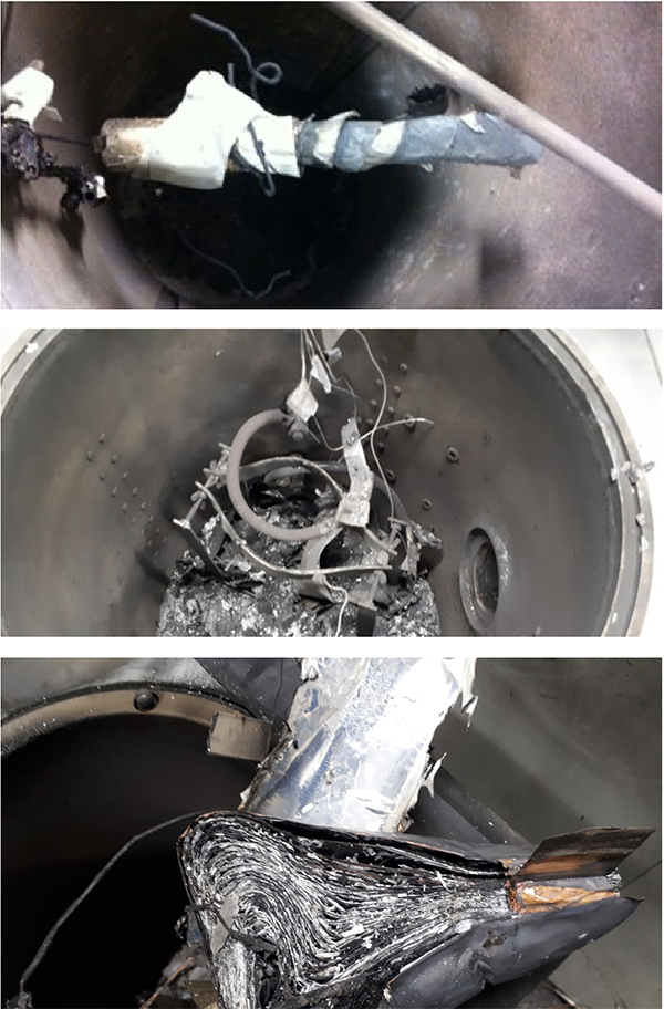
The most frequent abuse test performed in ARCs is the thermal abuse using the Heat-Wait-Seek (HWS) test. As soon as self-heating of the cell is detected, the heaters in the calorimeter chamber immediately follow any change of the cell temperature preventing the heat transfer to the chamber. Thus, the cell is heating up more and more until a thermal runaway occurs or the chemicals for this exothermal reaction are wholly consumed. Fig. 8 shows examples for cylindrical, prismatic and pouch cells after thermal runaway initiated by an HWS test in an ARC. For the Ramp Heating test, which mimics a Hot Box test, the cells are heated up at a constant rate instead of stepwise heating. For the Thermal Propagation test, a thermal runaway is initiated using one of the abuse conditions described above and the effect on the neighbouring cells is observed.
However, with the aim of the manufacturers to further increase the energy density of the cells, new abuse conditions are emerging because the limit of the electrochemical system of LIBs is reached. According to a recent article, recent results indicate that a new type of abuse condition, electrochemical abuse, is the underlying mechanism for the emerging causes of battery failure.2
On the one hand, the current research uses inherently safer materials and components for LIB design. On the other hand, it aims to quantitatively examine the temperature, heat and pressure values and the gases and smoke development and to determine the causes for battery failures. In addition, extensive (pre-normative) research is also being carried out to develop even more practice-relevant (standardised) safety tests.
Are electric vehicles less safe than vehicles with an internal combustion engine?
A battery that satisfies the relevant standards means that it will have an acceptable hazard level upon failure, and the probability of failure is significantly reduced. However, this probability will never be zero.
During mass production, defective products will always occur, and the standards cannot cover all possible triggering conditions in practical conditions. The current failure rate of electric vehicles is approximately 0.9–1.2 per 10,000 vehicles, according to the statistics reported by the National Big Data Alliance of New Energy Vehicles in China. Compared with vehicles with internal combustion engines (ICE) (which experience approximately 1.06 fire accidents per 10,000 vehicles in China and 7.3 fire accidents per 10,000 vehicles in the US), the current probability of accidents is low for electric vehicles.2
The main reason for fire accidents in ICE vehicles is the failure of electrical circuitry, which can then ignite combustible surroundings. However, such a fire is much easier to extinguish than that caused by thermal runaway in a battery. Therefore, in some cases, the consequences of electric vehicle fires might appear more dangerous. Fire extinguishing is significantly different compared to combustion cars because more water is required (10,000 litres for fire extinguishing and acute cooling) and because it might be difficult to even get to the well-protected battery.
There are regulations that require permanent cooling for 76h in water containers or quarantine of the electric vehicle in a so-called ‘Rescue Bag’. However, fortunately, in most cases, passengers could save themselves because the fire only reached the passenger compartment after a long delay after the fire started at the LIB. This means that the passengers were able to leave the vehicle on time. But it should be kept in mind that the gases, which can spread very quickly in the vehicle, are at least as dangerous as the effects of fire.
What can the consumer do to improve battery safety?
He should inform himself about the safe, regular use and the correct behaviour in the (unlikely) case of smoke, gas and/or fire development and under no circumstances should perform experiments on the cells or carry out changes to test the limits of the technology. Do not purchase counterfeit or ‘cheap’ batteries from third parties. Are there any good chargers for the battery? Use only original chargers and charging cables from the original manufacturer. He should use quick charging not too often for mobile phones, observe the temperature window (-25 to + 40°C), and operate the battery in an appropriate voltage window. Batteries should always be charged between 20 and 80%, stored at a suitable storage temperature of 15-20°C at 30-60% state of charge (e.g. for e-bikes). You should be cautious if you observe phenomena such as deformation (swelling), discolouration, heating, or an unusual sweet smell, which indicate that the battery is not working correctly anymore and its further operation could become unsafe.
Are LIBs safe?
The previous studies conclude that the safety risks associated with the use of LIBs are low. On the other hand, this applies if perfect cell production and the appropriate, i.e. responsible, use of cells, batteries and modules is guaranteed. Even in the case of accidents that cannot always be avoided, the safety measures are very good (delayed fire development, thermal propagation barriers, training of fire brigades).
References
1. The Innovation Platform, Issue 4, page 102: Innovative calorimetric methods for safer batteries in the renewable energy sector.
2. Wensheng Huang, Xuning Feng, Xuebing Han, Weifeng Zhang, and Fachao Jiang, Cell Reports Physical Science 2, 100285, January 20, 2021.