Professor John W Harris, Department of Physics at Yale University, and Dr Thomas Ullrich, Physics Department at Brookhaven National Laboratory, outline the key components of the Electron-Ion Collider (EIC) and what it will mean for physics research.
The Electron-Ion Collider (EIC) is being constructed in the U.S. to address fundamental questions about the inner structure of matter. What is the origin of the mass and spin of an atomic nucleus and how do the protons and neutrons within generate its properties? What role do the interactions of the quarks and gluons, which make up protons and neutrons inside the nucleus, play in producing these properties and those of other subatomic particles? Are their new states of matter to be found that emerge from a system of quarks and gluons?
After recommendation as the highest priority new facility in the 2015 US Nuclear Physics Long Range Plan and a positive endorsement from the US National Academy of Sciences in 2018, the EIC is being constructed at Brookhaven National Laboratory in the US. It is anticipated to commence operation and data taking in 2030. Proposals for a large integrated collider detector at the EIC are expected at the end of 2021. After ten years of R&D on detectors for the EIC, challenges still remain in defining a large ‘general purpose’ detector system and its components that will best reveal the answers that are being sought and potential new physics.
The EIC will collide electrons (e) with protons (p) or ions (charged atomic nuclei (A)) over a range of relativistic energies from around 20-150 times the energy equivalent of the proton mass. By measuring the kinematics of the scattered electron and the properties of the particles produced from the proton, detectors will be able to identify the three-dimensional structure of the proton in momentum and coordinate space, which is key to understanding how quarks and gluons contribute to its properties and more generally to properties of an atomic nucleus.
In addition to seeking answers to questions like those above, the EIC is expected to benefit various areas of science and technology.1 This includes not only the fields of nuclear and particle physics, but also astrophysics, accelerator physics, and computational modelling. Furthermore, the EIC continues to benefit from and enrich a variety of technologies from its detector and accelerator R&D and their designs. Industry also plays a role in aspects of the detector and accelerator development, fabrication and construction techniques, and implementation.
General detector constraints to achieve the science
Proposals for a ‘general-purpose EIC detector’ are being formulated, differing primarily in the capability of components to fulfil the requirements of the kinematic coverage for event topologies that are expected to address the science questions. A primary requirement is to detect and identify 2 the scattered electron with excellent momentum resolution. The scattered electron will be focused kinematically in the forward-going region of the incident electron (along the electron beam direction) and thus the primary electron detection will be concentrated in this region.
To detect and measure all other products of the reaction, primarily subatomic particles called hadrons, requires that the overall detector system have complete geometric coverage. This is called ‘hermeticity’. Thus, the design of the detectors and the detector magnet must be carefully integrated to ensure proper identification of the many different particles 3 and their momenta. This requires detectors inside the field of the magnet to register the tracks of the charged particles and will involve various types of identification techniques. Furthermore, calorimeters are required to measure the energies of neutral particles, typically outside of the magnet. To achieve optimum performance, the primary interaction point must be localised to within 20 microns and the material thicknesses of detector and support systems must be minimised to refrain from altering the original trajectories and momenta of the particles.4
Additional requirements are involved for the far-forward regions near the beam pipes, where particles with large momenta must be detected with precision at very small angles close to the collider beams in specialised detector systems. Among other challenges for the collider complex, there is the necessity for it to have high-precision luminosity measurements and polarimeters to monitor the intensities and spin orientation of the collider beams, respectively.
Detector concepts
EIC detectors will be large, complex instruments planned and realised by multi-institutional collaborations from laboratories and universities around the world. Many lessons have been learned from the first e+p collider, HERA at DESY in Germany, but the new EIC efforts also benefit from the enormous progress in detector technology made since HERA ceased operation in 2007. EIC detectors are expected to be located at two interaction regions (IRs), where the e and p or A beams are steered into collision. Space at the two IRs, labelled IP6 and IP8, is constrained substantially due to the arrangements of complex magnets that enable high luminosity 5 operation delivering higher data rates.
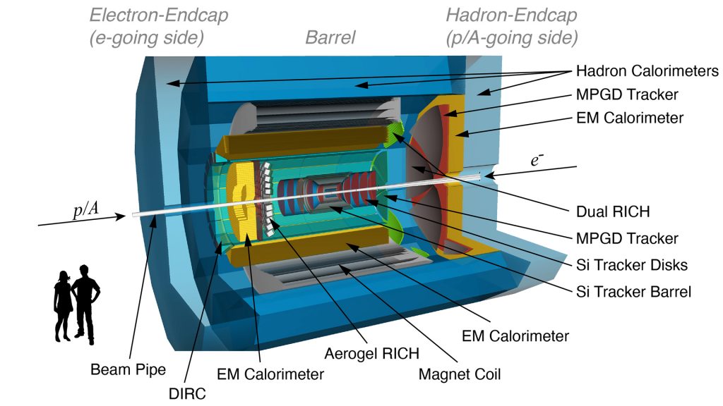
A general-purpose EIC detector as shown in Fig. 1 will consist not only of the ‘traditional’ central detector but will have strong integration of forward and backward subdetectors to determine the identity and momentum of the produced particles over a wide range of momenta from 100 MeV/c to 50 GeV/c.6 Other sophisticated scientific instrumentation is needed to measure the polarisation of the beams and luminosity with high precision. While only one general-purpose detector (to be located at IP6) is currently in the scope of funding for the EIC project, the scientific community strongly recommends the construction of two detectors to optimise the science output. This will lead to complementarity in detector acceptance and a reduction of systematic effects. It also would allow for the independent experimental verification required for scientific discoveries.
The design of a general purpose EIC detector calls for a solenoidal magnet, which ensures that the magnetic field does not alter the trajectories of the electron beam and thus avoids synchrotron radiation and excessive backgrounds. Various superconducting solenoidal magnet options are being investigated, including the reuse of an existing 1.5 Tesla magnet or the new construction of a larger 3 Tesla solenoid. The stronger the field, the better the precision of the particle momentum measurements. A solenoidal configuration leads naturally to subdetectors for particle tracking and identification, precise localisation of the interaction vertex, and calorimeter systems organised in a barrel design with endcap detectors.
In comparison to symmetric colliders, such as the Large Hadron Collider that collides p+p, the asymmetric nature of EIC collisions (e+p, e+A) leads to unique detector requirements. The detector systems in the p- or A-going side (in the Hadron-Endcap of the forward region) of the detector, the central region in the Barrel, and the e-going side (in the Electron-Endcap of the backward region) will see very different particle distributions in terms of the flux and types of particles and their momenta. For example, the p- and A-going side must detect the bulk of the produced hadrons with momenta up to ~60 GeV/c, with the scattered electron detected predominantly in the backward region.
This leads to unique challenges for the design of an EIC detector requiring:
- A nearly 4π hermetic detector that incorporates inner tracking devices of low mass to reduce multiple scattering and energy loss of the scattered electron;
- Excellent momentum resolution in the central and backward regions for precision measurements, especially of the electron momenta;
- High resolution tracking around the interaction point to measure particles containing heavy quarks that decay typically within ~100 microns of the collision vertex;
- Excellent measurement of particle energies by calorimeters in the forward region for hadrons and in the backward region for electrons; and
- Identification of particle species over a wide range
of momenta in regions:
Forward: up to 50 GeV/c;
Central: up to 8 GeV/c; and
Backward: up to 7 GeV/c.
This latter requirement for particle identification for a variety of particles and range of momenta is perhaps the most challenging requirement.
Particle tracking technologies
All current particle tracking solutions under consideration are based on a combination of subsystems that contain silicon semiconductor-based sensors and micro-pattern gas detectors (MPGDs). Silicon sensors provide resolutions of a few microns that allow tracking with the highest precision while maintaining a low material budget. The technology of choice for the EIC is Depleted Monolithic Active Pixel Sensors (D-MAPS). A third generation of these sensors is currently under development as a joint effort between the EIC and the ALICE Collaboration at CERN. In the central region, the Si tracker consists of up to six cylindrical layers of sensors mounted on boards (ladders) sitting on a rigid structure (staves) made of light composite materials. In the forward and backward regions, tracking is provided by disks equipped with silicon sensors as illustrated in the centre of Fig. 1.
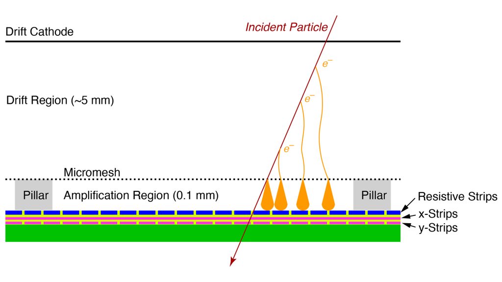
The disadvantage of silicon tracking is the high cost of sensors. Therefore, the layers and disks farther away from the interaction region will utilise micro-pattern gaseous detectors with technologies such as Gas Electron Multiplier (GEM), Micro Mesh Gaseous Structures (Micromegas), and Resistive Micro Well (µRWELL) some of which are already used for tracking in experiments around the world. These technologies typically combine a gaseous device for electron amplification with high granularity strips or pads on anode readout boards to provide a combined 2D space point resolution within ~50 microns, as seen in Fig. 2. These devices can be built to cover about a tenth of a square meter at a fraction of the cost of silicon devices. However, to construct large cylindrical detectors there are several R&D items related to their construction and performance that still require further investigation.
Particle identification techniques
A big challenge for EIC detectors is particle identification, driven by the need to distinguish electrons from pions, kaons, and protons with a separation purity of 99.8% in all regions. This can only be achieved by using dedicated particle identification detectors based on Cherenkov light emission and time of flight measurements. A particle that traverses a medium with a velocity that exceeds the speed of light in this medium 7 emits light at an angle that depends on its velocity. This light is called Cherenkov radiation. The characteristics of the medium (radiator) determines the threshold for this process to set in. EIC detectors use special gases, aerogel, and quartz as radiators to match the required momentum range of the particles that need to be identified. Tight integration with the tracking system is required since the originating track must be established to associate the produced Cherenkov light with its respective track.
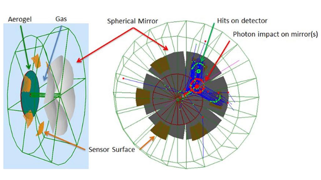
In the most challenging forward (A-going) region, the EIC foresees the use of a Ring Imaging Cherenkov Detector (RICH) with both gas and aerogel radiators to avoid gaps in coverage due to their different Cherenkov thresholds. In this dual RICH detector, shown in Fig. 3, the Cherenkov light is reflected by mirrors onto a plane and read out by photosensors. Light from the sample particle will form a ring whose radius, together with knowledge of its momentum, allows unambiguous identification of the species of the particle in the momentum range ~3-60 GeV/c.
An important feature of Cherenkov detectors emerges at high refraction index. Since both the Cherenkov angle and the angle for total internal reflection are solely dependent upon refractive index, one finds that, at normal incidence, Cherenkov light will be totally internally reflected. This feature implies that light can be propagated to the end of the radiator while preserving the Cherenkov angle. The result is a geometrically thin device that allows light detection only at one end. This type of detector is called a DIRC (Detection of Internally Reflected Cherenkov light) and will be used in the central (barrel) region of an EIC detector.
The original application of DIRC was in the BaBar experiment at SLAC, where the barrel section of the detector was surrounded by a series of radiator bars made of synthetic fused silica (‘quartz’) and rings were imaged by an expansion volume on one side of the bar. In the years that followed, many advances in DIRC technology have been accomplished and it is anticipated that the DIRC technology deployed at an EIC will far outperform the BaBar version, including a dramatically reduced size of the expansion volume. Particle identification will be possible up to 6-7 GeV/c with this device.
In the last few years, we have seen major advances in the precision by which detectors can measure the time-of-passage of a particle. This time, when compared to a reference time for the collision itself, the start time, and the knowledge of the path the particle took (tracking), allow for a measurement of the particle’s velocity. The velocity, together with the momentum of the particle provided by the tracking devices, fixes the mass of the particle and thus its identity.
These Time-of-Flight (ToF) detectors are usually very thin. One technology considered at the EIC is for the timing to be achieved with a silicon-semiconductor based technology such as Low Gain Avalanche Diodes (LGADs) that is intrinsically insensitive to magnetic fields. LGADs achieve around 30 pico-second (ps) resolution although with rather large spatial resolution. Recent research has studied how to segment LGAD sensors with pixels or strips with pitches in the tens of a micron in order to achieve fine spatial resolution while maintaining the fine LGAD time resolution.
A new technology, AC-coupled LGADs (AC-LGADs), was demonstrated to be a good prospect for ToF layers at the EIC providing time resolution in the few tens of ps and sensor segmentation of a few tens of microns. They are, however, thicker than the MAPS technology mentioned above, which could be problematic in regions where the highest tracking performance is essential. Even better timing performance than an AC-LGAD could be provided by Large Area Picosecond Photon Detector (LAPPD) devices providing timing resolution of about 5 ps. This novel detector is based on microchannel plate technology, but currently lacks the necessary pixelisation required for an EIC ToF detector. R&D to adapt the LAPPD technology for the EIC is under way.
Calorimeters, their development and implementation
Calorimeters are detectors that measure the energy of a particle. Particles that enter the calorimeter lose their energy via particle showers whose signal is measured. The size and strength of this signal reflects the energy of the particle, although only a fraction of its energy is sampled as the particle traverses the calorimeter. Calorimeters are typically segmented and constructed of individual blocks or towers. In the EIC, they will weigh up to hundreds of tons. The EIC uses two types of calorimeters, electromagnetic (ECAL) and hadronic (HCAL) calorimeters. The former is designed specifically to measure particles that interact electromagnetically, such as electrons and photons. The latter measures the energy of hadrons, such as pions, kaons, and protons that interact via the strong nuclear interaction.
Nearly all physics processes measured at the EIC require the detection of the scattered electron. Its momentum is measured using the tracker and its energy is measured with ECALs surrounding the inner barrel and endcaps. Excellent energy resolution of the ECALs is essential at small scattering angles, especially in the e-going (backward) region, where the momentum resolution of the tracker is insufficient due to the weak bending power along the axis of the solenoidal magnetic field.
The ECAL also aids in the separation of electrons from hadrons and in the detection of photons. Few technologies exist that fulfil the EIC’s requirements in the backward region. The most common choice is to use crystals made from Lead Tungstate (PbWO4). However, these crystals are expensive and require precise quality control in the manufacturing process, and thus few producers exist. An alternative material, scintillating glass, has been developed within the EIC R&D programme that can match the resolution of PbWO4 at a considerably lower cost. However, these have lower density requiring a longer calorimeter compared to crystals. Due to the limited space in certain regions of the detector, short radiation length materials are favourable with PbWO4 the only option.
A few other considerations for the ECAL in the different regions of the detector should be mentioned here. In the central region, the individual ECAL towers must point to the interaction point in a projective geometry. In the forward region, high granularity is required to resolve the pion’s decay photons where scintillator fibres made from tungsten powder developed in the EIC R&D programme will be used.
Hadron calorimeters are required to determine the total energy in hadronic particle jets (collimated showers of hadrons) and neutral particles that are not captured by trackers. For the HCAL, existing technologies are considered sufficient with the exception of the hadron-going (forward) region where further R&D is needed to optimise their performance. All HCAL devices at the EIC will be sampling devices. The absorber envisioned currently is steel, which can also serve as the return yoke for the magnet and improve its structural integrity.
Forward and backward auxiliary detector systems
Many of the exciting physics processes an EIC desires to study are in kinematic ranges that lie outside of the ‘main’ detector components discussed so far. Examples are the study of gluon saturation expected to more likely be observed in events where the electron scatters to very small angles within or near the beampipe or the study of diffractive events where the proton stays intact and deviates little from the beam direction. 2 These events must still be measured and the particle’s momentum determined at small angles. This requires specialised auxiliary detector systems that are installed in the forward and backward directions very close to, or even in, the beampipes. In the far-forward region, silicon detectors employing LGADs housed in vessels within the beampipe (called ‘Roman Pots’) can detect forward-going hadrons up to 5 mrad of the beam with the excellent timing resolution of LGADs. Very low-angle electrons will be tagged far-backward in position-sensitive detectors located close to the beampipe.
Neutrons and low-energy photons in the forward direction will be detected in the Zero-Degree Calorimeter (ZDC), with both ECAL and HCAL components. This allows not only tagging the nuclear breakup of the ion in e+A collisions but also determination of the centrality of the collision.2 To further study the nuclear breakup products, silicon detectors will be installed in the far-forward direction directly inside a large EIC beam magnet. In the far-backward region, bremsstrahlung photons can be detected in an electromagnetic zero-degree calorimeter, or a pair spectrometer that will be used to determine the luminosity of collisions in the EIC, which is needed for the normalisation of most measurements. In other sections of the EIC, electron and hadron polarimeters will measure the polarisation of the beams to a systematic precision better than 1%.
General design and integration
The baseline EIC configuration currently includes one fully instrumented Interaction Region (IR) with one general purpose physics detector. It is assumed that the detector will be located in IP-6 of the current RHIC complex. A possible second detector can be housed in IP8. In both cases, much of the infrastructure of the current RHIC experiments, STAR in IP6 and sPHENIX in IP8, can be re-used. Detector subsystem infrastructure requirements include various types of cooling, power, cryogenics, cabling, service lines, and gas support systems for gaseous detectors. These requirements cannot be specifically identified at this stage but will be developed in the near future.
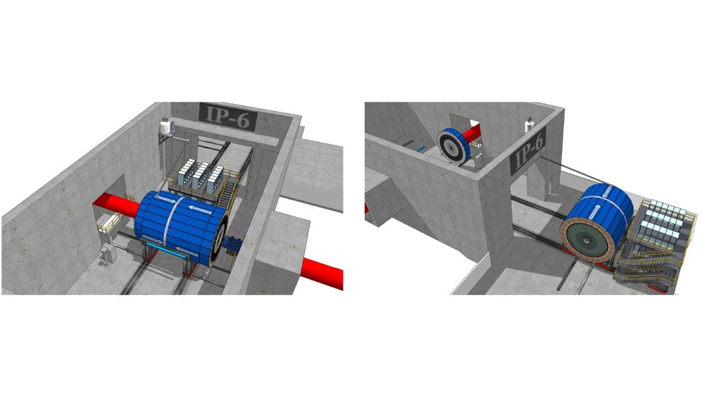
In addition to the beam line area in IP6, the area has an assembly building with adequate floor space for detector maintenance work, as well as a control room, counting house, office space, electronic/mechanical workshops, gas shed, online computing room, and other service areas. Fig. 4 depicts the EIC detector at IP6 in the experimental hall for operation and in the assembly hall for maintenance.
Summary
The EIC has been approved by the U.S. Department of Energy for construction, with an expected start in 2030. The Brookhaven and Jefferson National Laboratories have made a call for detector proposals that are due in December 2021. It is anticipated that an international detector committee will make a recommendation on detectors in the two interaction regions of the EIC in early 2022. One detector is within the funding scope of the EIC Project, while a possible second detector would require additional funding from throughout the international community.
There are currently three ‘proto-collaborations’ that have formed, with intentions on proposing an EIC detector. One called ATHENA is based on a large 3 Tesla magnet, another called CORE on a small compact 3 Tesla magnet, and a third called ECCE on the reuse of an existing 1.5 Tesla magnet. All three detectors are of solenoidal design and incorporate many of the design requirements, technologies, and features presented in this article.
Acknowledgements
This work was supported by the Office of Nuclear Physics in the Office of Science of the U.S. Department of Energy.
References
1: See ‘Science Requirements and Detector Concepts for the Electron Ion Collider,’ EIC Yellow Report, R. Abdul Khalek et al, 2021, https://arxiv.org/pdf/2103.05419.pdf
2: An essential requirement is to be able to identify electrons and suppress misidentification to less than 1/10,000
3: Efficient identification to better than three standard deviations for particle momenta up to 7 GeV/c in the central region and 50 GeV/c in the forward region for hadrons, which are primarily pions, kaons, and protons
4: This is a ‘material budget’ corresponding to an interaction length in the central detector system of less than 5%
5: Luminosity at particle colliders is proportional to the number of collisions that occur per unit time
6:An electron-Volt (eV) is the kinetic energy gained when an electron accelerates from rest through a potential difference of 1 Volt. The unit eV/c corresponds to momentum, MeV/c and GeV/c to 106 and 109 eV/c, respectively
7: The speed of light in a given medium is cmedium= cvacuum/n, where n is the index of refraction of the medium
Please note, this article will also appear in the eighth edition of our quarterly publication.